
How equipment connects
to the facility.
Rack power, cooling connections, controls and maintenance access all affect the facility design.
THE PHYSICAL FOUNDATION
From the campus
to the cold plate.
Explore the layers around the compute. Follow the power supply and the cooling path as the scale changes.
SITE & POWER
Start with the site.
A development plan connects the utility interface, buildings and supporting systems. The tenant’s equipment requirements shape the facility brief.
- Facility interface
- Site rights, utility connection, phasing and access.
Illustrative equipment and interfaces, not a Lintel installation or an engineering design. Projects are under development; responsibilities and specifications are agreed per project.
Utility supply ≠ critical IT load.
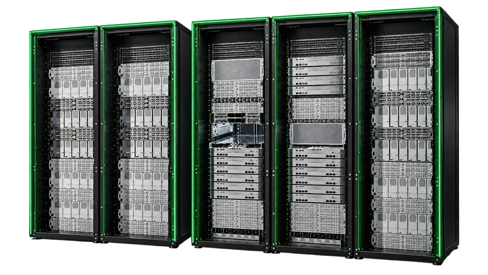
What matters
Utility supply serves the whole facility, including cooling and other building systems. Critical IT load is the power required by the IT equipment.
What to check
Connection voltage, capacity, timing, metering, resilience and phased demand.
Documents
Utility information, the electrical design basis and remaining approval conditions.
Electrical planning records and original diagram
From utility supply
to critical IT load.
The utility connection serves the whole facility. Critical IT load is the power required by the IT equipment. Keep the two boundaries explicit in capacity and phasing discussions.
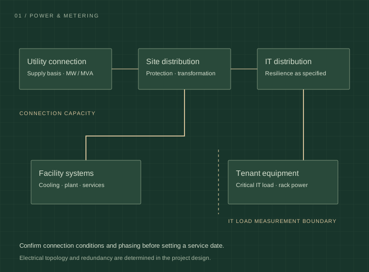
- 01Connection basis
- Supply capacity and voltage; connection point; utility conditions; metering boundary; energization date and confirmation status.
- 02Electrical interface
- Tenant equipment load and rack power; protection and distribution; resilience requirements; room for later phases.
- 03Project record
- Site and power assessment, an electrical design basis, and a schedule of open utility and permitting conditions.
From cooling plant to rack.
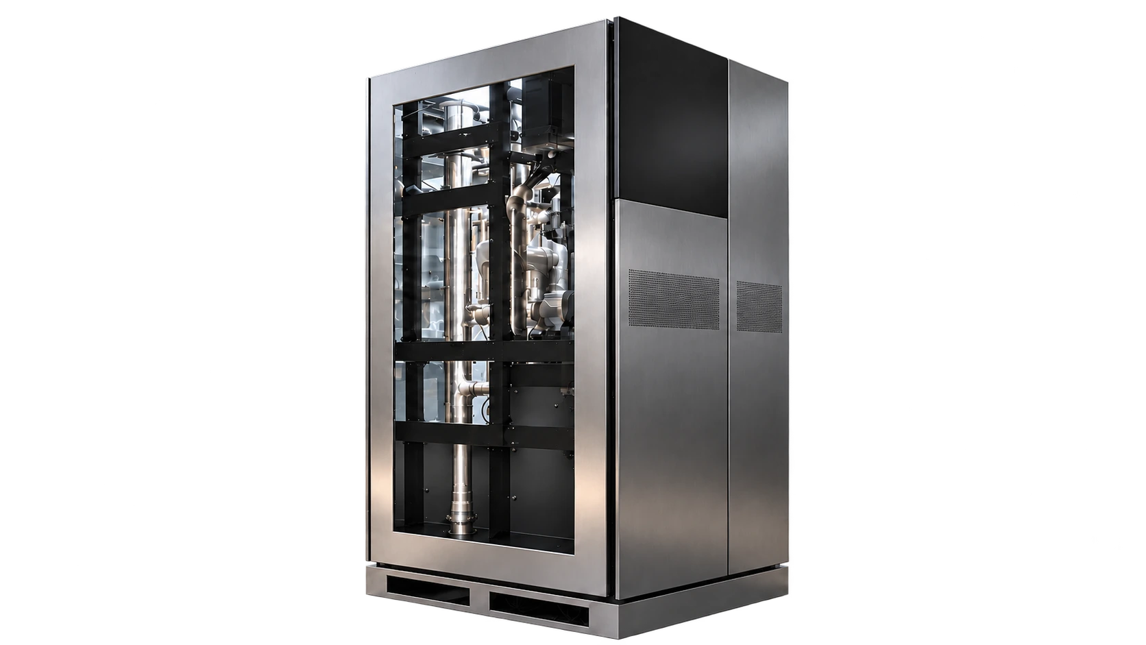
What matters
Selected hardware sets the heat load and operating envelope.
What to check
Supply and return temperatures, flow, pressure, fluid quality, controls and access.
Documents
Manufacturer references and a project-specific cooling interface schedule.
Cooling planning records and original diagram
A cooling chain,
with defined boundaries.
GB300 combines liquid and air cooling. Vera Rubin uses a fully liquid-cooled architecture. Specify the selected platform’s heat load, coolant and operating envelope across the facility plant, CDU and rack.
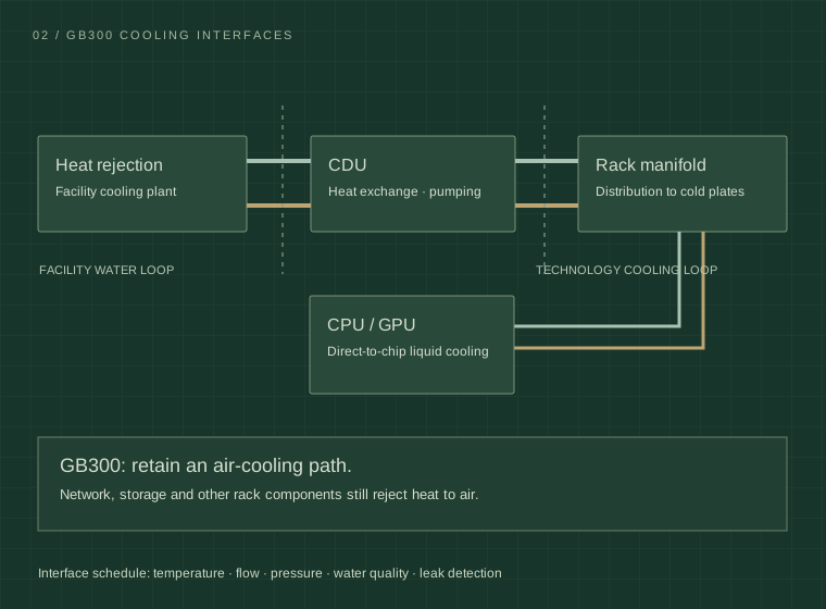
- 01Liquid-cooling interface
- Supply and return temperatures, flow rate, pressure, fluid quality, isolation and leak detection requirements, confirmed against the selected equipment.
- 02Space & connectivity
- Rack layout and maintenance clearances; pipe and cable routes; fiber entry and network rooms; residual air-cooling demand.
- 03Project record
- Equipment schedule, cooling interface schedule and coordinated facility layout, with design responsibilities and acceptance criteria.
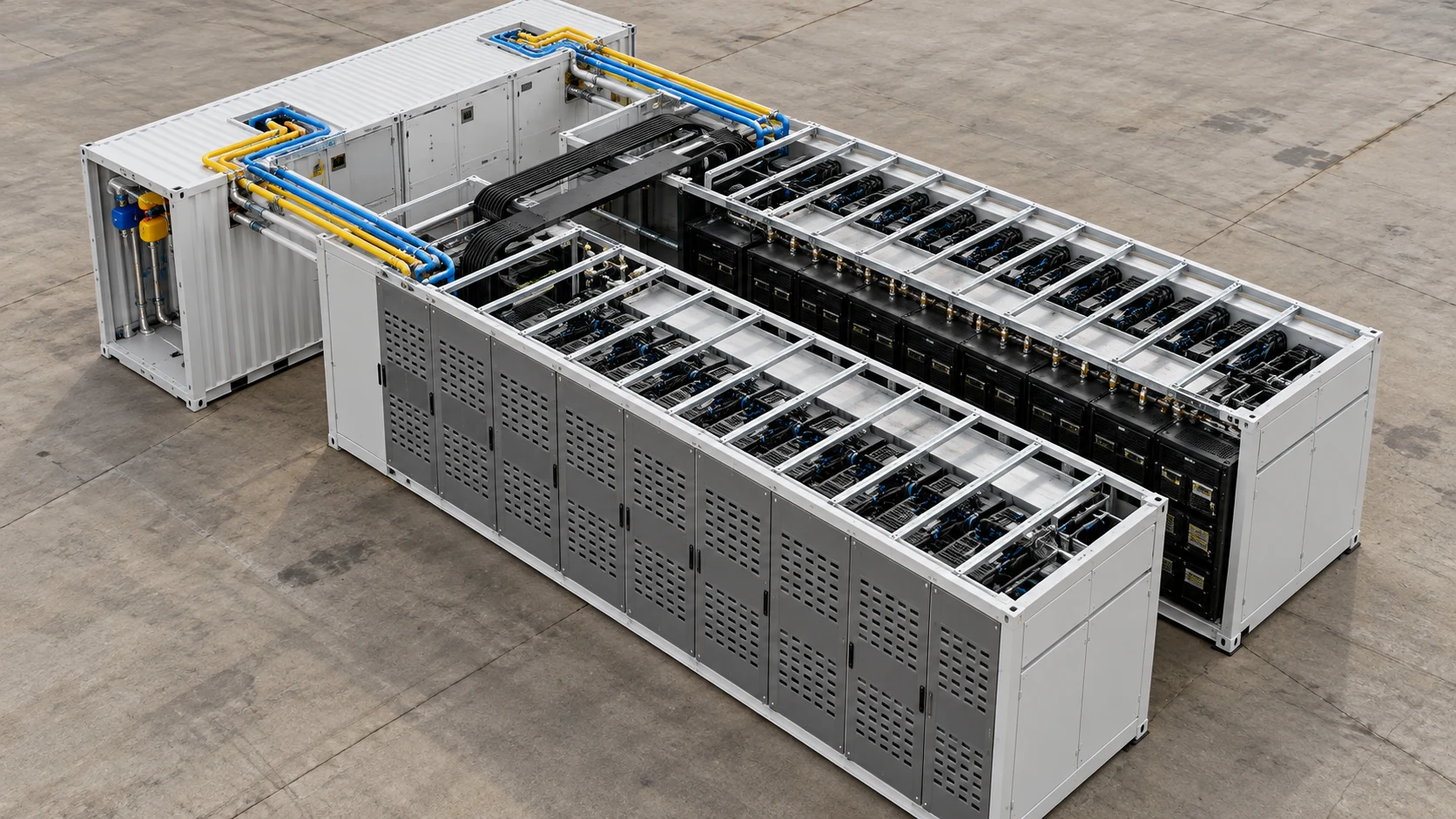
Connecting modular systems.
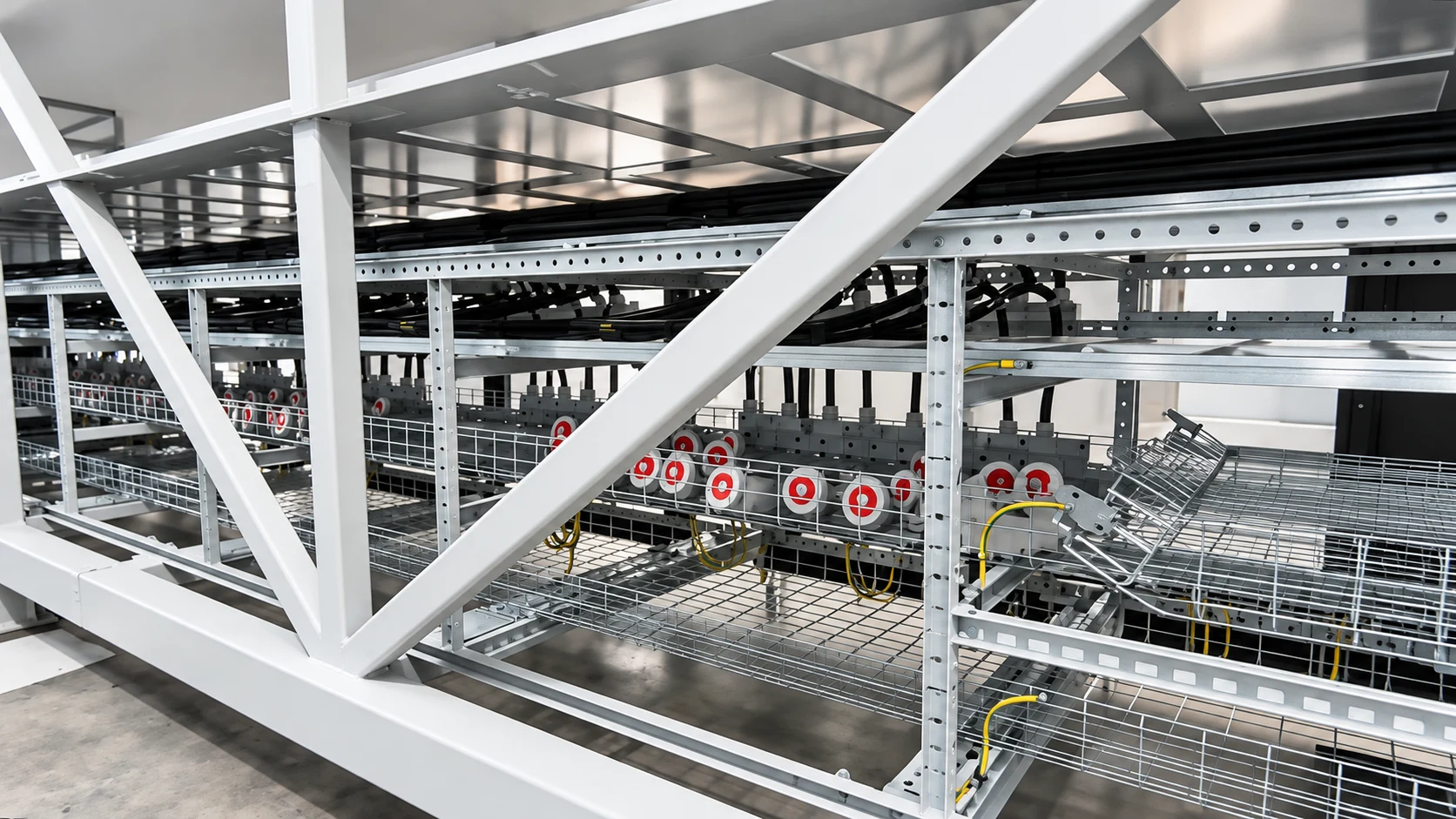
View a modular cutaway concept
What matters
Prefabricated equipment still needs site works, installation and connections.
What to check
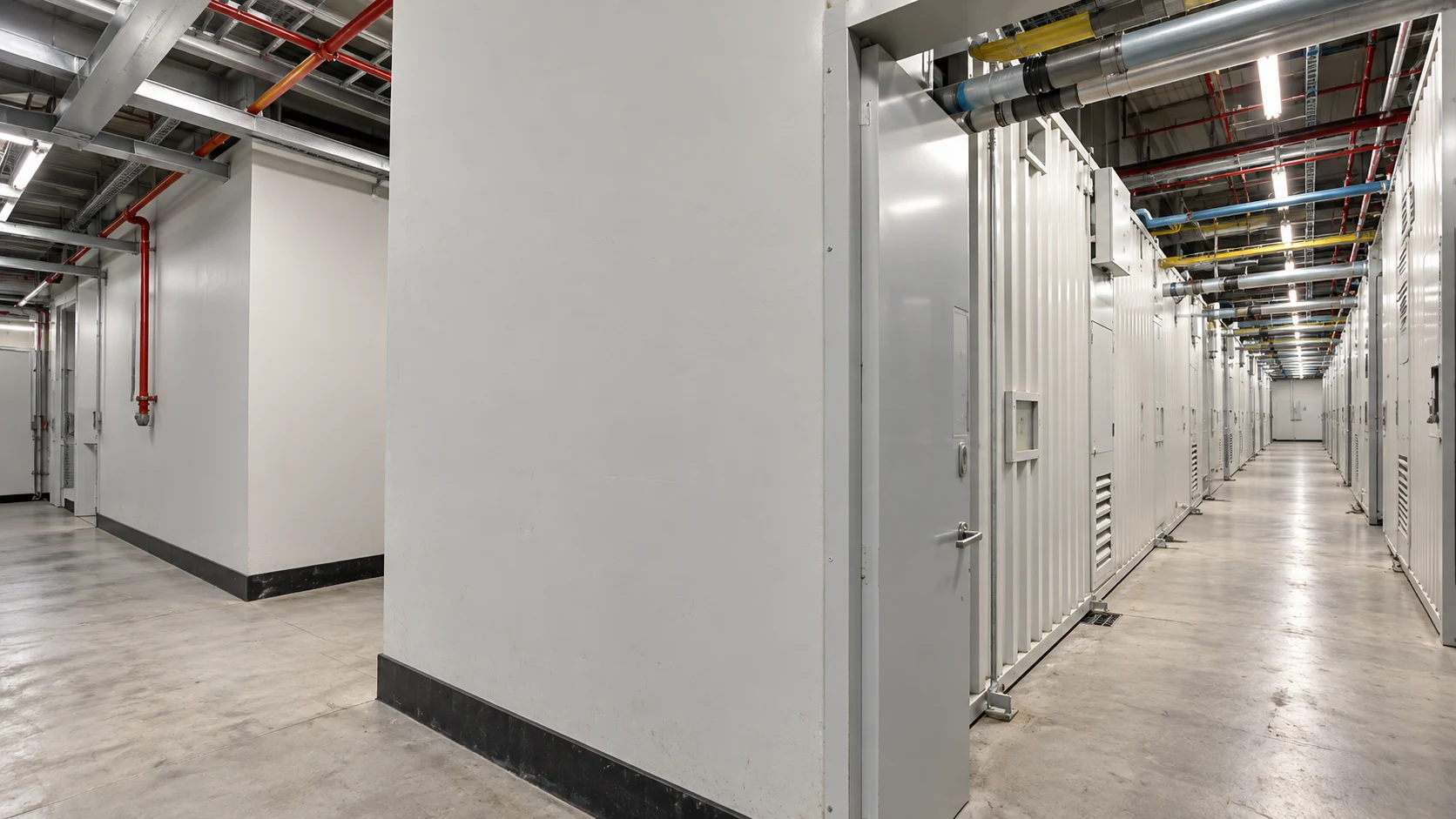
Space, transport, lifting, cabling, fibre routes, network rooms, pipework, controls and maintenance access.
Documents
Coordinated layouts, supplier scopes and agreed interface tests.
Tests to agree before handover.
Technical requirements
List the electrical, cooling, controls and equipment conditions to test at each connection.
Acceptance basis
For each test, agree the method, acceptance criteria, measurements to record and how exceptions will be handled.
Handover
Record who conducts and accepts each test, when it takes place, and what remains unresolved.
Handover planning records and original diagram
Make readiness
measurable.
The service date depends on the connection, permits, equipment and construction programme. Define the evidence required at each handover.
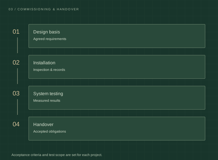
- 01Before construction
- Agreed design basis, responsibility matrix, equipment scopes and project approvals; a programme showing utility and long-lead dependencies.
- 02Before service
- Installation inspections, agreed system tests and commissioning results; a register of unresolved items and acceptance conditions.
- 03Operating handover
- Accepted results, equipment and maintenance records, operating responsibilities and the conditions for the next development phase.
GB300 liquid cooling.
Start at the rack.
Public reference architectures help make a tenant discussion concrete. The selected hardware and project design establish the actual requirement.
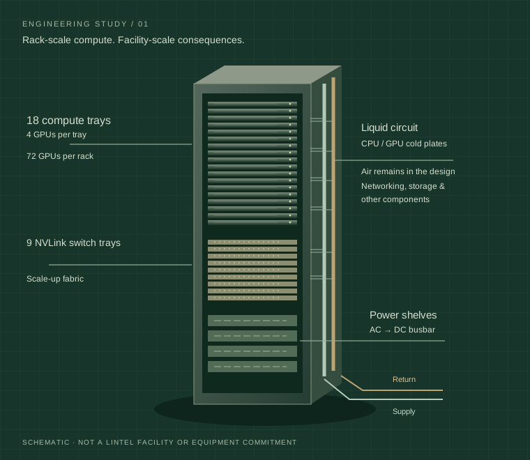
NVIDIA DGX GB300 NVL72 / reference configuration
Grace CPUs per reference rack
Blackwell Ultra GPUs per reference rack
- Compute
- 18 compute trays; four GPUs per tray.
- Scale-up network
- Nine NVLink switch trays, fifth-generation NVLink.
- Scale-out network
- ConnectX-8 interfaces support 800 Gb/s networking.
- Rack power
- AC power shelves feed a DC busbar.
- Heat removal
- Liquid cooling for CPUs and GPUs, with air cooling for other components.
Technical reference: NVIDIA GB rack hardware guide ↗. Published reference equipment; these figures do not describe Lintel capacity.
From a rack to a cluster +
NVIDIA’s DGX SuperPOD reference architecture uses eight DGX GB300 racks per scalable unit and specifies 1.2 MW TDP for the unit, including network, management and storage systems.
The unit’s TDP covers the combined equipment architecture. It is not a utility connection requirement, a Vera Rubin specification or a Lintel project capacity.
Read the NVIDIA SuperPOD architecture ↗A different generation.
A different thermal basis.
Vera Rubin infrastructure belongs in the facility brief from the start. Its full-liquid architecture requires a fresh equipment and cooling schedule, with electrical and mechanical interfaces confirmed for the selected system.
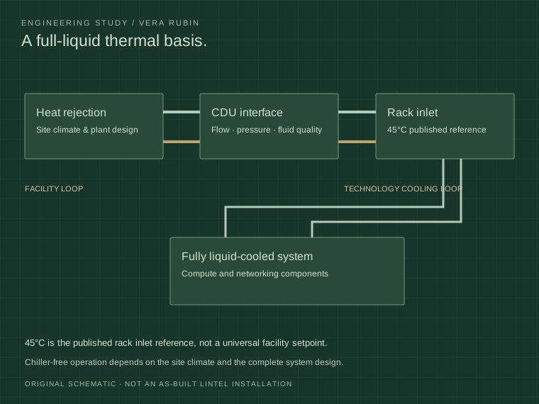
NVIDIA Vera Rubin NVL72 / published reference
Published inlet reference · NVIDIA AI factory specification
Liquid-cooled system architecture
- Compute & fabric
- 72 Rubin GPUs and 36 Vera CPUs, connected through sixth-generation NVLink.
- Cooling basis
- Full-liquid system cooling replaces GB300’s hybrid thermal arrangement. Confirm inlet temperature, flow, pressure and fluid requirements with the selected equipment supplier.
- Facility consequence
- Evaluate heat rejection against local weather and the operating envelope. Dry-cooler or chiller-free operation depends on climate and system design.
Sources: NVIDIA Vera Rubin specifications ↗ and NVIDIA liquid-cooling architecture ↗. Reference parameters are not a Lintel performance, water-use or capacity guarantee.
Keep each platform’s design basis separate.
Liquid cooling for CPUs and GPUs, with a remaining air-cooling load. Coordinate both paths.
Vera RubinFull-liquid system architecture. Revalidate the thermal and electrical interfaces for the selected configuration.
Sources behind the engineering studies.
- NVIDIA / GB300 NVL72 ↗
72 Blackwell Ultra GPUs and 36 Grace CPUs per reference system. Checked 19 October 2026.
- NVIDIA / DGX GB300 hardware guide ↗
GB300 rack configuration and cooling arrangement. GB rack guide updated 17 September 2026.
- NVIDIA / DGX SuperPOD reference architecture ↗
Eight-rack scalable unit and its equipment-level TDP boundary. GB300 reference architecture, checked 18 October 2026.
- NVIDIA / Vera Rubin NVL72 ↗
Rack configuration, sixth-generation NVLink and 45°C inlet reference, with the vendor’s at-scale AI factory qualification. Checked 19 October 2026.
- NVIDIA / Full-liquid cooling architecture ↗
Rubin thermal architecture and the climate conditions for dry cooling. Published 21 June 2026.
- Schneider Electric / Reference Design 109 ↗
GB200-based public example of facility power, liquid cooling and IT-space coordination. Used for interface methodology, not as a GB300 or Vera Rubin equipment specification. Published 14 March 2026.
- Lintel / Public company overview ↗
Development scope, tenant brief and project responsibility structure. Version 0.15.1, 30 October 2026.
Engineering diagrams are original explanatory studies. Reference equipment, vendor designs and development documents do not represent a completed Lintel project, a certification or a capacity commitment.
The architectural study.
Explore the original Lintel campus model, from site and power to the inside of the facility. This is a conceptual study, not a completed or owned facility.